
Benefits of an Aspheric Lens:
1, Spherical Aberration Correction
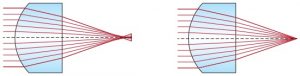
The most notable benefit of aspheric lenses is their ability to correct for spherical aberration, an optical effect which causes incident light rays to focus at different points when forming an image, creating a blur. Spherical aberration is commonly seen in spherical lenses, such as plano-convex or double-convex lens shapes, but aspheric lenses focus light to a small point, creating comparatively no blur and improving image quality. Spherical aberration is inherent in the basic shape of a spherical surface and is independent of alignment or manufacturing errors; in other words, a perfectly designed and manufactured spherical lens will still inherently exhibit spherical aberration. An aspheric lens can be designed to minimize aberration by adjusting the conic constant and aspheric coefficients of the curved surface of the lens.

2, Additional Performance Benefits
To achieve the required performance of an imaging lens, optical designers often have to stop down, or increase, the f/# of their design. While this may achieve the desired resolution goal, this technique results in a loss of light throughput. Utilizing aspheric lenses in the design, however, improves aberration correction and makes it possible to design high throughput systems with low f/#s, while simultaneously maintaining good image quality. The table below compares an 81.5mm focal length, f/2 triplet lens consisting of all spherical surfaces, versus the same triplet with an aspheric first surface. Both designs use the same glass types, effective focal length, field of view, f/#, and total system length. The table quantitatively compares the modulation transfer function (MTF) @ 20% contrast of on-axis and off-axis collimated, polychromatic light rays at 486.1nm, 587.6nm, and 656.3nm. The triplet lens with the aspheric surface shows greatly increased imaging performance at all field angles as indicated by high tangential and sagittal resolution values, by factors as high as four, compared to the triplet with only spherical surfaces.

| Object Angle (°) | All Spherical Surfaces | Aspherical First Surfaces | ||
| Tangential (lp/mm) | Sagittal (lp/mm) | Tangential (lp/mm) | Sagittal (lp/mm) | |
| 0.0 | 13.3 | 13.3 | 61.9 | 61.9 |
| 7.0 | 14.9 | 13.1 | 31.1 | 40.9 |
| 10.0 | 17.3 | 14.8 | 36.3 | 41.5 |
3, System Advantages
Aspheric lenses allow optical designers to correct aberrations using fewer elements than conventional spherical optics because the former gives them more aberration correction than multiple surfaces of the latter. For example, in zoom lenses where ten or more lens elements are typically used, two aspheric lenses can be substituted for a handful of spherical lenses in order to achieve similar or better optical results, while reducing system size and potentially reducing the overall cost of production.
Anatomy of an Aspheric Lens
The term asphere encompasses any lens with surfaces that are not portions of a sphere. However, when we use the term here we are specifically talking about the subset of aspheres that are rotationally symmetric optics with a radius of curvature that varies radially from the center of the lens. As discussed earlier, aspheric lenses improve image quality and reduce the number of required optical elements. From smart phones and laser-enabled devices to high-end microscope objectives and surgical equipment, aspheric lenses are increasingly critical to every facet of the optics, imaging, and photonics industries due to the distinct advantages that they offer compared to traditional spherical optics.
Aspheric lenses have been traditionally defined with the surface profile (sag) given by Equation 1:
(1)Z(s)=Cs21+√1−(1+k)C2s2+A4s4+A6s6+A8s8+...Z(s)=Cs21+1−(1+k)C2s2+A4s4+A6s6+A8s8+...
Where:
Z = sag of surface parallel to the optical axis
s = radial distance from the optical axis
C = curvature, inverse of radius
k = conic constant
A4, A6, A8...= 4th, 6th, 8th… order aspheric coefficients
When the aspheric coefficients are equal to zero, the resulting aspheric surface is considered to be a conic. The following table shows how the actual conic surface generated depends on the magnitude and sign of the conic constant, k.
Conic Constant Conic Surface
k = 0 Sphere
k > -1 Ellipse
k = -1 Parabola
k < -1 Hyberbola

Aspheric surfaces can also be specified using the orthogonal coefficients Qbfs and Qcon. Aspheres described using these coefficients are called Q-type aspheres. The Qbfs coefficient describes the RMS slope departure of the aspheric surface from a best-fit sphere. This departure can be easily calculated and provides a useful quantification of how easy it will be to test the surface. The Qcon coefficient describes the sag departure of the aspheric surface from a base conic. These Q-type aspheres described by Qcon and Qbfs give designers more control over the optimization of the aspheres. They also reduce the number of terms needed for manufacturing, thereby avoiding unnecessary complications for fabrication, simplifying testing, and reducing cost.
The most unique geometric feature of aspheric lenses is that the radius of curvature changes with distance from the optical axis, unlike a sphere, which has a constant radius. This distinctive shape allows aspheric lenses to deliver improved optical performance compared to standard spherical surfaces.

Asphere Manufacturing Methods
1, Precision Glass Molding
Precision glass molding is a manufacturing technique where optical glass cores are heated to high temperatures until the surface becomes malleable enough to be pressed into an aspheric mold. After the cores cool down to room temperature, the resulting lenses maintain the shape of the mold. Creating the mold has high initial startup costs because the mold must be precisely made from very durable material that can maintain a smooth surface, while the mold geometry needs to take into account any shrinkage of the glass in order to yield the desired aspheric shape. However, once the mold is finished the incremental cost for each lens is lower than that of standard manufacturing techniques for aspheres, making this technique a great option for high volume production.

2, Precision Polishing
For decades, machined aspheric lenses have been ground and polished one lens at a time. Although this process of individually producing machined aspheres hasn’t changed dramatically, significant fabrication technology advancements in precision polishing have elevated the achievable level of accuracy possible from this production technique. In precision polishing, small contact areas on the order of square millimeters are used to grind and polish aspheric shapes. These small contact areas are adjusted in space to form the aspheric profile during computer controlled precision polishing. If even higher quality polishing is required, magneto-rheological finishing (MRF) is used to perfect the surface using a similar small area tool that can rapidly adjust the removal rates to correct errors in the profile. MRF technology provides high performance finishing in less time than standard polishing techniques because of its precise control of the removal location and high removal rate. While other manufacturing techniques generally require a special mold unique to each lens, precision polishing utilizes standard tooling, making it the best option for prototyping and low-to-medium volume production.


3, Diamond Turning
Similar to grinding and polishing, single point diamond turning (SPDT) can be used to manufacture single lenses one at a time. However, the tool size used in SPDT is significantly smaller than in precision polishing, producing surfaces with improved surface finishes and form accuracies. Material options are also much more limited with SPDT then with other techniques because glass cannot be shaped through diamond turning, whereas plastics, metal, and crystals can. SPDT can also be used in making metal molds utilized in glass and polymer molding.
4, Molded Polymer Aspheres
Polymer molding begins with a standard spherical surface, such as an achromatic lens, which is then pressed onto a thin layer of photopolymer in an aspheric mold to give the net result of an aspheric surface. This technique is useful for high volume precision applications where additional performance is required and the quantity can justify the initial tooling costs. Polymer molding uses an aspheric mold created by SPDT and a glass spherical lens. The surface of the lens and the injected polymer are compressed and UV cured at room temperature to yield an aspherized lens. Since the molding happens at room temperature instead of at a high temperature, there is far less stress induced in the mold, reducing tooling costs and making the mold material easier to manufacture. The thickness of the polymer layer is limited and constrains how much aspheric departure can exist in the resulting asphere. The polymer is also not as durable as glass, making this is an unideal solution for surfaces that will be exposed to harsh environments.

5, Injection Molding
Injection molding allows for the optimization of part cost, complexity of tooling, and precision. Plastic injection molding involves injecting molten plastic into an aspheric mold. Since plastic is not as thermally stable and resistant to pressure as glass, it must be specially treated in order to create a usable aspheric lens. Plastic lenses also have a lower scratch resistance than glass lenses. However, plastic lenses are advantageous because they are light-weight, easily molded, and integrate with mounting features to create a single element. While the selection of optical quality plastic is limited, the cost and weight benefits will drive some designs toward plastic aspheric lenses.
Plastic aspheres can also be formed using compression molding, where a preheated plastic material is placed in the open lower half of a mold before the top half of the mold is pressed down - compressing the plastic to match the mold shape. Compression molding is used for lenses where structure detail is important, such as in Fresnel lenses and lenticular arrays. Injection and compression molding techniques can be used separately or combined. When combined, the technique is commonly referred to as coining.
Advantages of Each Type of Asphere
Precision Glass Molded Ideal for high volume production requirements because rapid production of many lenses allows for amortization of large up-front tooling charges.
Precision Polished Ideal for prototypes or low to mid-volume requirements because of short lead times and low tooling costs. Also ideal for the highest performance requirements.
Polymer Molded An ideal alternative to Glass Molding for mild aspheric departures or mid-volume production.
Injection Molded Ideal for volume production as a weight-sensitive, low cost alternative to glass aspheric lenses.
Tolerances on the Aspheric Surface
Surface accuracy
Surface accuracy is a measure of how accurately the optical surface matches its designed shape. There are a variety of ways of defining surface accuracy and the errors to the surface shape. They are grouped into three categories based on their frequency across the surface of a part: form errors, waviness, and surface roughness.
Form error, or irregularity, is typically the most important and commonly specified surface specification for aspheres. This specification consists of low frequency or larger errors usually peaking one to three times across a part. Form errors are typically specified as peak- to- valley error in waves or fringes, but can also be specified as a linear deviation in microns or as an RMS deviation.
Waviness, or mid-spatial frequency error, describes ripple-like errors happening in a frequency of 5-100 instances across the part and is most often introduced when a surface is polished with small polishing tools. This rarely happens in whole-aperture polishing performed when making spherical optics. Because of this, waviness is typically ignored in spherical lenses but may need to be specified in aspheres. Waviness is most commonly defined as a slope error over a specific scan length. Waviness sensitivity is application specific and many lenses are not sensitive to it, therefore it is important to only specify a waviness tolerance if the tolerance will affect your application. When adding additional lens requirements, costs can increase due to added testing.
Surface roughness, or high frequency error, is a measure of smoothness, or the quality of the polish on an optic’s surface. Surface roughness can effect scatter and the ability to withstand high laser power on the surface. To define surface roughness, it is important to describe both the amplitude and the frequency range of interest as the choice of test equipment may filter out high frequencies. Analyzing surface roughness requires very special testing and can be time consuming; therefore it is best to only specify surface roughness when necessary.
Radius
Radius error, a specific subset of form errors, is a constant change in radius across the lens. It is the most common and also generally the easiest error for a system to tolerate since it is typically corrected by adjusting the focus position. Radius error can be defined as a percentage change in radius from the design radius, a linear change in radius, or as fringes of power. Manufacturing costs for a lens can be reduced by allowing a looser radius tolerance.
Metrology
Proper metrology is necessary to ensure an asphere meets all required tolerances. The two most common measurement techniques for surface accuracy or figure error are interferometry and profilometry.
Interferometry measures the difference between a reference wavefront and the wavefront reflected off a surface or transmitted through an optic. Testing an aspheric wavefront is much more difficult than testing spherical wavefront due to the difficulty of generating an aspheric reference wavefront compared to the common practice of generating a spherical wavefront. It is possible to test an asphere using a spherical reference wavefront if the asphere has deviations from a sphere smaller than the dynamic range of the interferometer, but this is seldom the case for aspheres.
Null interferometry is a branch of interferometry which is either done by using null lenses or computer generated holograms. A null lens is a spherical lens, or an assembly of spherical lenses, designed to have an amount of spherical aberration equal to the departure from a sphere of the nominal aspheric surface. The amount of interference observed shows the deviation between the real aspheric surface and the nominal surface. Computer generated holograms (CGH) use holography to generate the desired wavefront when a special plate is placed in the reference path of the interferometer. Null interferometry is expensive and time consuming to set up because it must be carefully calibrated for the shape of the specific aspheric surface being tested, but afterwards it can be used to quickly and accurately test many identical aspheric surfaces.
Stitching interferometry is a branch of interferometry in which a small section of the aspheric surface is tested with a spherical wavefront. If the deviation from a sphere is smaller than the dynamic range of the interferometer over a small area, a measurement can be made using a spherical wavefront over that region. Measurements from many small sections are stitched together to give a complete map of the surface. There are several methods of stitching and each vary by the sections they divide a surface into. All stitching methods have limitations on the shapes they can test and are restricted to surfaces without inflection points where the local radius of curvature goes from a positive to a negative radius. Stitching interferometry has a faster set up time than null interferometry, but the test time per part is more than that of null interferometry because multiple sections of the lens must be tested.
Profilometry measures the change in height of a lens by moving a probe across the surface. This is usually done in spirals or slices across the surface, building a cross section or a surface map of the height. Slices are normally quicker to measure but do not provide full surface information. Profilometry is more simple and flexible than interferometry, but is not as accurate. The limitations on shapes a profilometer can test is typically only limited by the slope of the part, while features such as inflection points do not limit the profilometer. Set up time is typically short for a profilometer, but scan time can vary depending on the number of scans or area scanned.