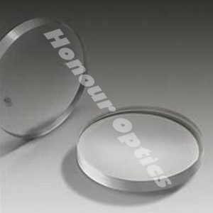

Optical designers have dealt with trying to compensate for spherical aberrations in their systems for centuries and will continue to do so as improvements in emerging technologies push the limits of optical components. Additionally, optical designers and manufacturers continue to look for designs that reduce aberrations as well as new components that eliminate spherical aberrations all together. With the advent of doublet lenses and aspheric lenses, many optical designers are able to compensate for spherical aberrations within their system during the early stages of design. However, industrial end-users and laboratory researchers often do not have a simple or cost effective solution which easily compensates for these errors.
Current aberration correction methods include the use of adaptive optics: more specifically, deformable mirrors or liquid lenses. The current state of these technologies require the end-user to have an in-depth knowledge of electro-optics and computer programming to successfully integrate a closed loop adaptive optics system. This makes it extremely difficult to quickly and easily improve system performance. Spherical aberration compensation plates represent a truly unique, passive solution for correcting spherical aberrations.
The component nature of the corrector plates drastically increases the product line's lifetime and overall usability. They can be integrated into a system at any point during the production or use-cycles. As a passive optical component, software and electronic advancements do not reduce or restrict the lifetime and usefulness of these products. As long as diverging or converging light is sent through glass spherical aberrations will continue to be a concern for optical designers and industrial end-users. These characteristics make spherical aberration plates a mainstay in the optics industry for years to come.
To truly understand and appreciate the benefits of incorporating spherical aberration compensation plates into an existing application setup, consider two real-world examples with accompanying equations, illustrations, and Zemax simulations.
Application 1: Spherical Aberration as a Function of Beam Diameter and Wavelength
Spherical aberration compensation plates specify the total amount of spherical aberration imparted on a collimated beam of light covering its entire clear aperture. However, it is often necessary to know the amount of spherical aberration generated by the corrector plate at beam diameters smaller than its clear aperture. If the beam diameter is smaller than the clear aperture, then consider the question, "How much spherical aberration is generated?"
For a collimated beam, the total wavefront error, W(λ,ρ), generated by the corrector plate is a function of both the wavelength and incident beam diameter:
W(λ,ρ)=W040ρ4
where W(λ,ρ) is the transmitted wavefront error (WFE) due to spherical aberration in units of waves, or λ; ρ is the incident beam diameter divided by the clear aperture of the plate; and W040, which depends on wavelength, is the wavefront aberration coefficient based on the individual plate in units of λ.
Application 2: Correcting Aberration from a Positive Focal Length Optical Lens
A positive focal length optical lens always introduces positive spherical aberration. This is evident from its transmitted wavefront error (WFE) profile and optical path difference (OPD) graph. To correct the positive lens' induced spherical aberration, use a negative spherical aberration compensation plate.
It is important to note that because the spherical aberration compensation plate was placed in collimated space, the transmitted WFE is independent of the orientation of the aspheric surface on the plate. If the plate is added on the side of the lens where light is converging, then the amount of spherical aberration added by the plate is equal to the amount of spherical aberration produced by a plane parallel plate of the same thickness as the corrector plate plus the amount added if it were used in collimated space. To further understand this concept, consider the amount of induced spherical aberration for a plate placed in a convergent/divergent wavefront:
![]()
where W(λ, ρ, t, n, f/#) is the transmitted WFE due to spherical aberration in units of waves, or λ; ρ is the incident beam diameter divided by the clear aperture of the plate; W040, which depends on wavelength, is the wavefront aberration coefficient based on the individual plate in units of λ; t is the thickness of the plate; n is the index of refraction of the plate at wavelength λ; and f/# is the f-number of the convergent/divergent beam.
Optical aberrations exist in all optical, imaging, and photonics systems. The key to achieving the best systems is to understand and correct for these aberrations with the best methods and components. Spherical aberration compensation plates are one of the tools with which optical designers can save in design time, reduction of system weight and manufacturing costs. Spherical aberration compensation plates correct for known amounts of spherical aberration within a system, thereby allowing the implementation a single optical component without requiring a complete system redesign.